Chapter 3 – Part four: A central metropolitan block
The design for complete redevelopment: 331–334
the area, even when redeveloped completely, would still have to depend very largely upon public transport to bring in the working population and the shoppers.
The design for complete redevelopment
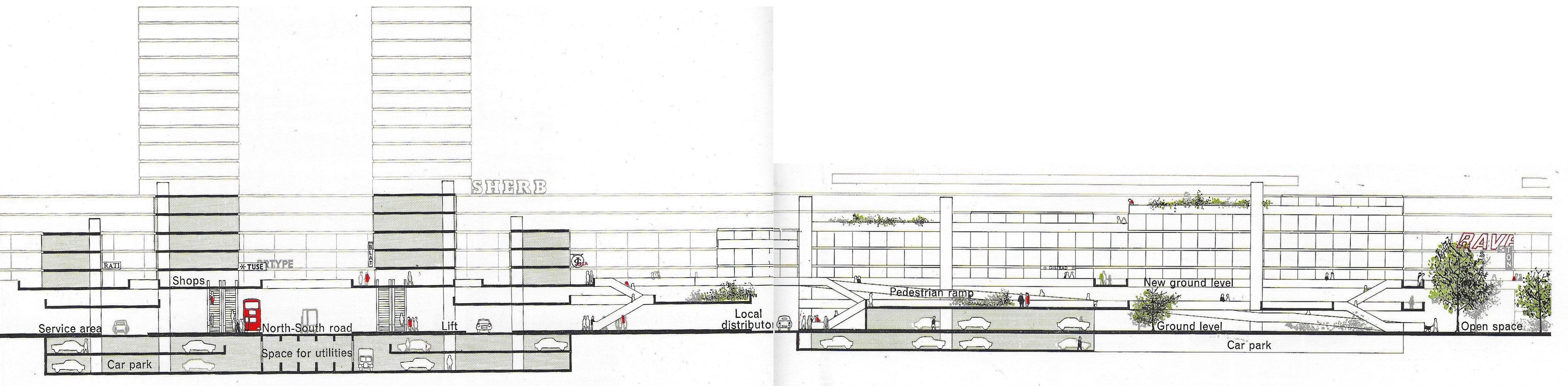
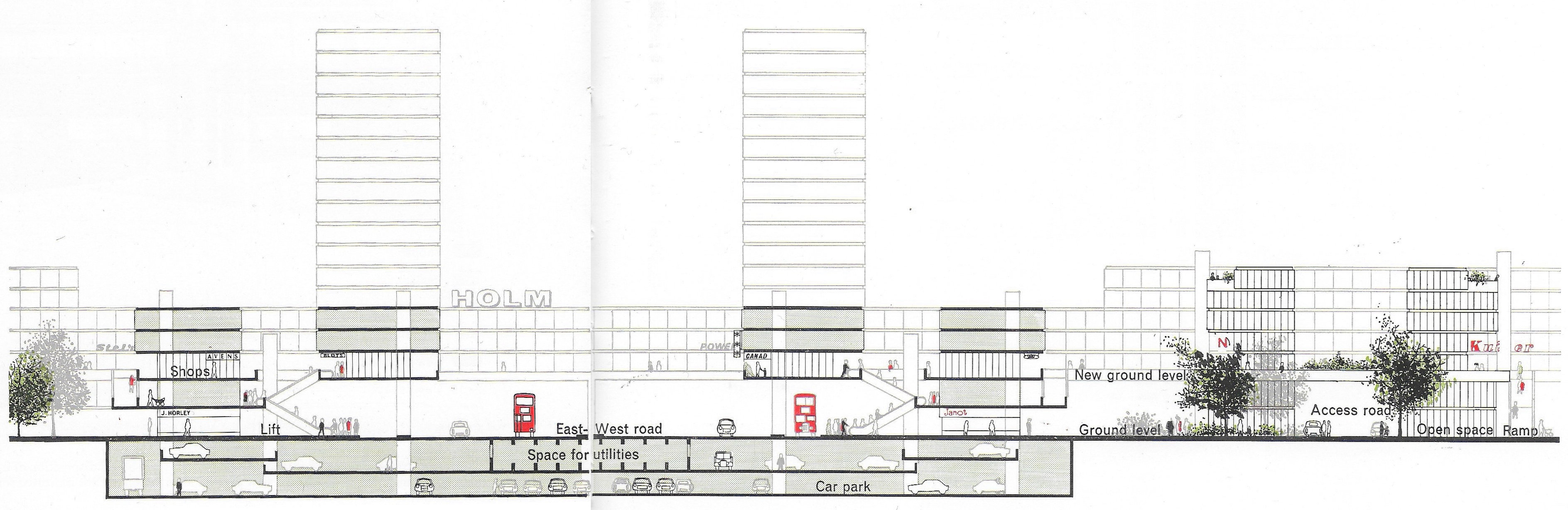
331The decision to place the busy district and local distributors at ground level, the considerable areas required for parking, garaging and servicing, the decision to ‘spread’ the parking rather than to concentrate it, the need to avoid excessive excavation of the site for parking purposes, and the desire to create a good environment for pedestrians, all led inevitably to a design with a pedestrian circulation system set above the traffic. This would in effect become the ‘new ground’ level for city life, a platform from which the buildings would rise. The car parking and the service areas would be underneath the buildings that is, with access at the original ground level. In the design as it emerged, however, there was nothing resembling a solid deck or platform. The ‘new ground’ proved to have a complicated lacework pattern like a sheet of metal out of which stampings had been punched, a criss-cross of building sites and pedestrian ways with frequent openings to let light, air and views to the lower level, and with the pedestrian system descending at many points to open spaces on the original ground (Figure 181).
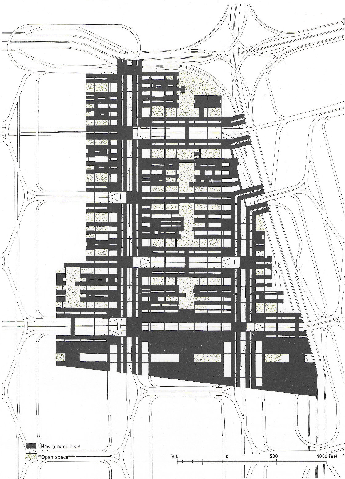
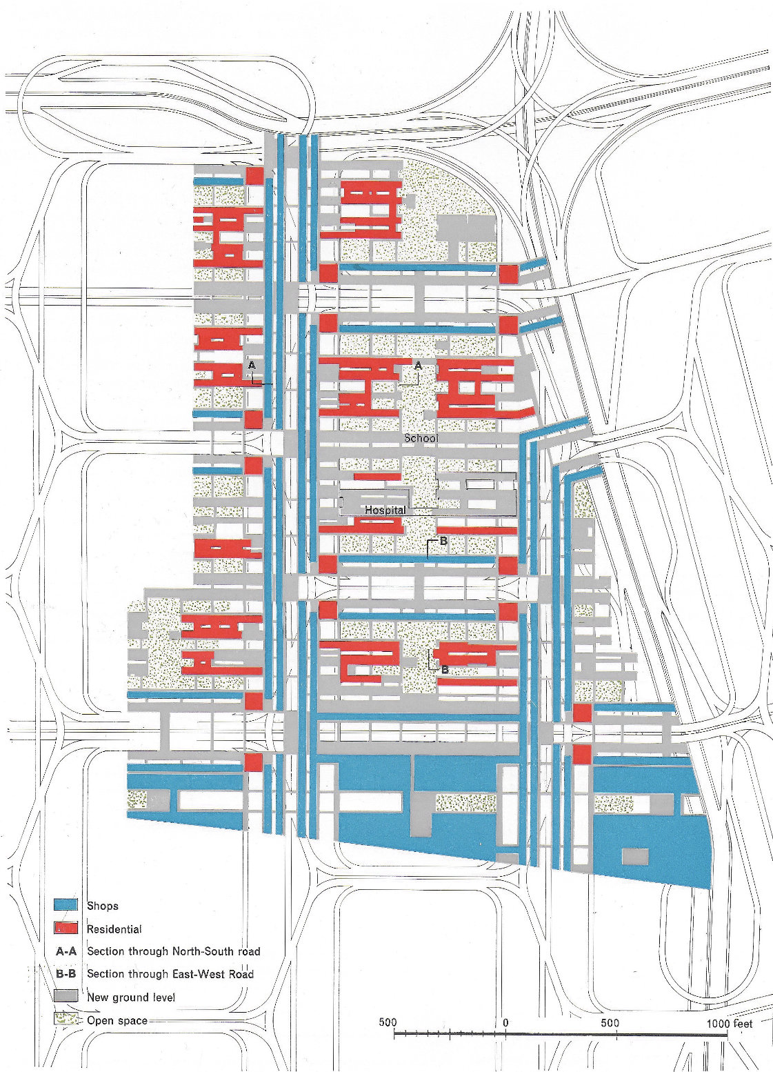
At first glance there appears to be very little resemblance between Figure 181 (‘new ground’ level) and Figure 180 (real ground level, showing distributors and access roads). The whole pattern and grain of the two plans seems entirely different. This illustrates the flexibility for design which results from the basic decision to create a pedestrian environment above the main traffic level. But, of course, there is a close relationship between the two levels. At the southern end of the site there are extensive platforms on which would be replaced the shops and stores from the north side of Oxford Street. Parking spaces would be provided underneath the stores, and also at several other levels. Access into the various parking areas from the primary distributor via the spur road would be very direct. Running northwards from the main shopping centre, and directly above the zig-zag line of the secondary distributor formed out of the two western sides of the hexagon, is a corridor or core of local shops. This corridor consists of two galleries 50 feet apart, centred on the zig-zag road, with frequent pedestrian bridges linking the two sides, on which small shops and kiosks are grouped. There is another similar corridor above the zig-zag distributor on the eastern side of the site, and further shopping corridors above the two east-west links of the hexagons. But these links would be noisy two-way roads and therefore the corridors have been made wider with the shops facing away from the road. The groups of bachelor dwellings are sited at nodal points where the two routes meet (Figure I85). Figure I83 shows a section through the north-south hexagon road and Figure 184 a section through the east-west road.
333The hospital is re-established approximately in its present position, with open space around it. The main groups of industrial and commercial buildings and show-rooms occupy sites running at right angles to the shopping corridors. In the centre of the area there would be some ground-level open space – a very urban kind of space, but possibly with forest-sized trees. Some of the family dwellings would be grouped around it. Given a continuation of this kind of development to adjoining areas, then footways and buildings could flow right over the primary distributors. (Figure 182 shows the location of shops, dwellings and open space.)
The outline we have given of the traffic calculations shows quite clearly that the area, even when redeveloped completely, would still have to depend very largely upon public transport to bring in the working population and the shoppers. The hexagonal distributors would provide convenient local bus routes with stopping places underneath the buildings. Access could be arranged to longer-distance or regional bus services on the primary distributors. The five existing underground stations would be directly linked with the pedestrian level.